
What is the problem with these oscillators?
Even though the Permeability Tuned Oscillators (PTO) by Collins are amazing creatures, they do not age well. The original tuning range of Collins PTO 70E-15 is 2…3 MHz corresponding exactly ten turns of the oscillator tuning shaft. There is, however, something unfortunate in the material parameters of the ferrite slug that makes the tuning range narrow. After decades of ageing, ten turns of the oscillator shaft may only produce, say, 990 kHz frequency difference. This leads to an inconveniently large inaccuracy on the frequency display of the receiver known as the end-point error. There is, however, an adjustment coil in the oscillator for correcting the end-point error. Unfortunately, the error invariably grows so large that the correction range is not sufficient.
A good account of this phenomenon and a repair is proposed in [1] already in 1969. My purpose is now to show in detail how this repair can be done successfully. In addition to basic tools, at least an oscilloscope, a stabilised anode/filament power supply, and a frequency counter is needed. Having access to a 3D printer or a lathe will make constructing the calibration jig much easier.
And a friendly warning: Please, do not even try this if (i) your condition is not suitable for high voltage work, or (ii) if this would be your first attempt at precision work and electromechanical repairs.
Description of the oscillator and repair of electronics
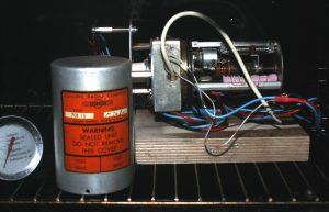
Because I want to have the Collins 51J-4 receiver in use during the reconditioning of its VFO, I acquired another unit (SN M7682 ) from eBay. The seal of the unit was broken and the silica gel packet had been removed. Apart from this, the oscillator seemed to be intact though dirty.

The first step is always the same: cleaning up the unit, careful inspection, and replacement of components that are likely candidates for failure. In the case of this PTO, there are two cathode bypass capacitors C-005 and C-006 (of brand Vitamin, 10nF each) and a feedback capacitor C-008 (Silver Mica of unknown brand, 10nF). The noncritical bypass capacitors were replaced by sufficient ceramic capacitors, but the feedback capacitor must be a higher quality component.
I acquired a handful of military-grade 1nF silver-micas from the Soviet Union: the green component seen in picture below. That 1nF capacitance is enough, is reported in the article [1]. One should observe that using a capacitor with higher losses may lead to lack of oscillation, according to some comments in the internet.
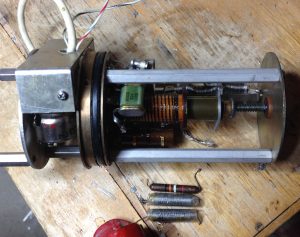
The PTO has two tubes, each 6BA6, of which one is the oscillator and the other is the buffer amplifier. Their emissivity of was tested and found satisfactory. Now, ready to power it up.
When powered by Farnell Instruments Ltd model E350 with B+ = 150.0 V and filament voltage 6.3 V, no smoke was observed, and the oscillator produced good sinusoidal waveform without glitches as seen on the oscilloscope. The frequency stability after many hours of warming appeared to be more than satisfactory even though the downward creeping during the first power-up seemed to be endless. Tube emissivity and moisture, perhaps? The frequency sensitivity was measured to be +3 Hz / V between B+ = 145…155 v.
So, the hardware is ready to go, and it is time to dig up the tuning fork.
Construction of a tuning jig
When the objective is to accomplish precision, the preparations are always the most time consuming stage.
The end-point error of 8 kHz over the range of 1 MHz corresponding to ten revolutions of the oscillator shaft add up to an error angle of ca. 30 degrees. To push the end-point error under 300 Hz will make it necessary to accurately measure an angle of less than 1 degree. Later, the scale nonlinearity error should be reduced under 300 Hz per each revolution corresponding 100 kHz as well. So, a measurement jig has to be improvised so that error angles less than, say, 0.3 degrees should be easily measurable.
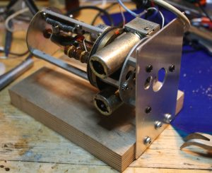
The oscillator installed to a simple jig made of plywood and aluminium plate. Europeans, please note that the oscillator screws are not metric.
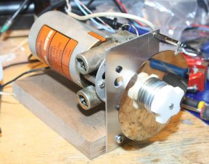
The oscillator shaft is glued to a plastic part produced by 3D printing. The graticule plate is from a defunct hard disk. Also, the tuning knob was 3D printed from a parametric model found in Thingiverse.
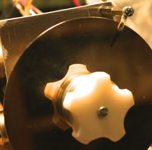
A solder tag is used for aligning after full turns an engraved thin line on the disc. Now we are ready to start the calibration.
Correction of the end-point error
After removing the hermetically closed shielding screw from the end-point adjustment coil, one should carefully make the adjustment screw (attached to the ferrite slug) mobile. Do not use anything chemical that would not evaporate by itself. Trying to remove the end-point error by tuning the coil will not be successful but it is a good idea to try it anyway. Then you, at least, know how much end-point error you have.
To reduce the inductance of the calibration coil (shown in front in the following picture), some wire will have to be removed. This unit had 7 kHz end-point error to begin with, and removing slightly under one turn from the coil was sufficient. Fig. 2 in [1] is useful for estimating the number of turns to be removed.
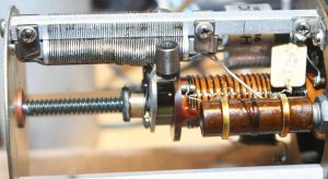
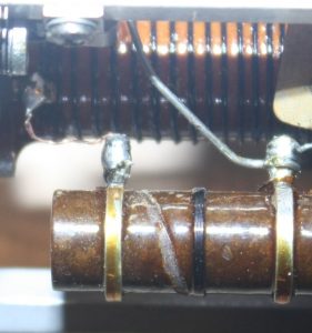
Above picture: The adjustment coil in its original state. Below: A close-up after reduction of one turn. After removing the wire, use, e.g., cyanoacrylate glue to stabilise the wire.
After trial and error, one should be able to reduce the end-point error by the adjustment screw to under, say 400 Hz. There is no point in trying to get it much better than that for the reason that the next step will also change the end-point error within the limits of a few hundred Hz.
Calibration of the scale linearity
There is a stack of metal shims inside the oscillator whose purpose is to change the rotation angle of the ferrite slug with respect to the oscillator shaft. Repositioning the shims is the means of attaining scale linearity over the range of 10 turns of the oscillator shaft. Without repositioning, the oscillator is expected to have a nonlinearity error of several kHz in different parts of the frequency scale even though its end-point error was insignificant.
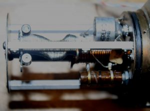
The stack of shims are shown in the picture above. There is a screw at the back end of the oscillator that releases the shims for calibration.
The first step is to align all the shims in the centre position, and then measure the frequency error at each full rotation of the oscillator shaft between the frequencies 2…3 MHz, eleven measurements in total. Mark the position of the rollers following the stack of shims (shown above) corresponding to each multiple of 100 kHz between 2…3 MHz, produced by the oscillator. Note that you can reliably measure the oscillator frequency only if the metal cover is installed.
It is easy to conclude which direction the stack of shims should be moved based on the sign on frequency error at the multiples of 100 kHz. Eleven interpolation points seems to be sufficient. After a few iterative steps, the shims should form a nice “mathematically smooth and regular” curve corresponding the frequency error profile.
The maximum frequency scale error of the oscillator shown here ended up being in the class of 100 Hz. Much better does not seem to be achievable (neither needed) since there is some backlash in the screw that drives the ferrite slug.
Drying and hermetically closing the oscillator
It is easy to sew and fill a small pocket (made of cotton fabric) by silica gel, and then desiccate the pocket in a microwave oven. Depending on power, some 10-15 mins. is enough.
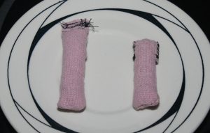
One pocket is tied inside the oscillator as shown in the next figure. One must check that the movement of the oscillator slug mechanism does not get impeded by the silica gel pocket. Then it is time to bake it. A safe temperature is below 60 deg. C, and one should use some thermometer instead of relying the thermostat of an electric oven. I used about three hours baking time, after which I let it cool inside the oven.
Closing the oscillator when hot will develop under pressure (unless the gaskets are leaky), making it perhaps impossible to get the cover open again. I used silicone oil to lubricate the gasket.
The next step is to let the PTO age by running it a few weeks. A stabilised voltage source for B++ = 150.0V and a frequency counter is required. I set the oscillator at 2500.000 kHz and started making notes. Note that the oscillator frequency is quite sensitive to the filament voltage, and if one of the 6BA6’s has poor emission, most any high power home appliance switched on will drop the grid voltage enough to change the oscillator frequency by several tens of Hz. The PTO is also sensitive to temperature: cold spraying the cover will soon drop the frequency by several tens of Hz.
After the first 24 hours, the set frequency had increased some 300 Hz. After 10 days, the increase was around 1.7 kHz. At that stage, I checked the end point error which had increased from 300 Hz to 2.4 kHz. The working hypothesis is that the observed drifting is secondary to a process that leads to end point error. However, the end point error is now increasing in the opposite direction compared to the starting point: 10 turns of the shaft will produce the range of about 1002.5 kHz. This is, perhaps, an indication that the hermetic sealing is successful, and that some oscillator components are returning to original material parameters values it had when new. This kind of end point error can be compensated by the external adjustment (unless too much wire was taken from the coil).
After two weeks of ageing, the PTO frequency still increases about 40 Hz / 24 h. I have decided to wait and see how things develop before final adjustments and the installation to 51J-4.
[This is work under progress. 15.4.2017.]
References:
[1] http://www.collinsradio.org/wp-content/uploads/2012/04/New_Life_for_51J_PTO.pdf