
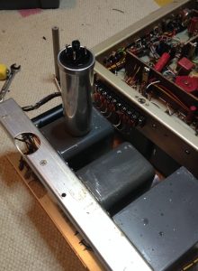
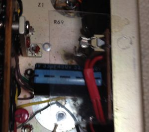
It must have been a glorious sight when this rig was cooked but I was not around watching. One of the chokes (the grey rounded cubes in the picture below) or the filter capacitor got short-circuited first, and then the other two followed. The choke in the middle had sprayed its paraffin insulation out from its casing all over the chassis.
Luckily, the net transformer was OK as well as the fuse. Net transformers are particularly difficult to obtain or rebuild.
Rebuilding cooked-up power sources of any tube equipment may well be dangerous, and all the usual warnings apply. So, consider yourself as being warned if you try it yourself. I do not recommend it at all. Even trained electricians mess up things properly every now and then. (Even presidents mess up things. Badly, as we have seen. They do.) My instructions are not complete, so don’t follow them. These are not even instructions, they are just a theoretical treatment.
I don’t trust you. Please, kill yourself somewhere else another day.
Equipment sine qua non: Isolation transformer. Variac, or at least a watt meter, preferably both. Multimeter.
Don’t power it up without a good reason. Why would you do that if you already know that both the smoke and the paraffin are out? There is nothing new to be learned, only more damage to be caused.
Those components should be removed that are obviously well done (in this case, one of the chokes). All capacitors will be replaced anyway, one cannot save here even if some of them appear to be functional. Then the other choke (with paraffins still inside) will also have to go since its internal DC resistance appears to be too low, and its poles are resistively connected to ground.
Almost everything has to go.
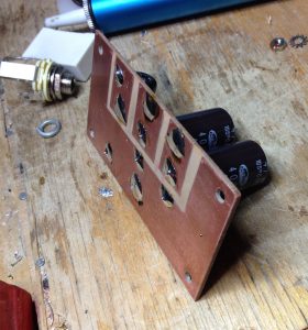
The new capacitors are much smaller than the original cans. A small piece of PCB is required to keep them reliably in position and isolation. This is definitely not a place for Vero board or tie-wraps.
Original type chokes are not available. Coiling new chokes to old cores is an option but recommendable only for purists that want to make museum quality restoration work. I am not one of them. I use whatever money can buy because it is cheap if you can just buy it.
Some people even restuff the old electrolyte or bathtub oil capacitors which I do not recommend at all for health reasons. After all, equipment is intended for use — not for display — and it is enough if the component and work quality in on par with the original.
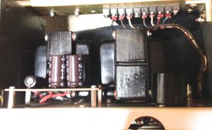
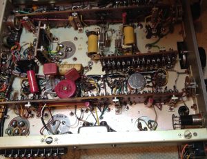
In the above picture, the new capacitor PCB has been installed as well as the two new filter chokes. The chokes are Hammond brand with inductances 12 H, 100 mA and 20 H, 100 mA. The original parts were identical 15 H, 85 mA units of brand TMC.
When choosing the values of new capacitors and chokes, one can use ripple voltage calculators in the internet to check that the new filter configuration is comparable to the original. Using chokes with lower internal DC resistance will inevitably increase the output voltage of the source. That problem will be dealt with later.
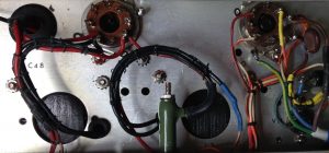
In equipment several decades old, it is a good idea to check the insulation of the wiring and the rubber bushings. When the original wire bundles have to be opened, it is a good idea to lace them back together. Not having the original material — waxed thread — available, good use can be made of polyester thread and few droplets of cyanoacrylate glue. Plastic cable ties… maybe not. Also, the power cable was replaced and a new cable clamp was installed as well. The one who does not know the rules for making ground connections should not be doing this…
After checking the new power source circuit with the ohm meter and comparing with the schematics, any obvious short-circuits were not found.
After replacing a few electrolytes on the converter side and adding a fuse to the anode line, it is time to power it on. I used a isolation transformer and an inexpensive watt meter intended for domestic use. A volt meter was also clamped to B+ line to measure the over voltage.
The unit becomes alive, takes some 15 W more power than it should. Some 40V too high B+. In a few moments, the power consumption starts suddenly rising. After quickly switching off, the audio tube 6AQ5 is found to be very hot.
So, the unit was powered on successfully, and sufficient new information was found. The next step is to achieve such state of repair that the unit can be kept powered indefinitely for measurements, trouble shooting, and alignment.
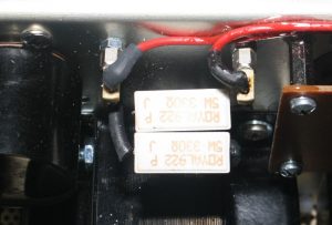
Using Ohm’s law, a first estimate for the voltage drop resistor to the B+ line is computed. Because the load is not resistive, the right value of the resistor must be sought by trial and error. The value of 155 Ohms seems to be good. Ceramic holders for the resistor are installed in a place with good air circulation as shown in picture below.
Reconditioning and alignment of the RF part
Now that the “creative” part of the repair work is ready, it remains to do the usual stuff to the electronics and the alignment. I give only a brief description.
All resistors in the circuitry are checked, and a couple of them get replaced. Special attention given to the usual trouble makers: cathode bias, grid leak bias, and screen resistors.
Short-circuits in grid coupling capacitors are sought after but none found. Paper capacitors are changed to polyester, no questions asked. There is one paper capacitor at 1 uF which gets replaced by an electrolytic capacitor.
The 1/4″ mono earphone jack is changed to stereo. The relays switching between USB and LSB modes couple intermittently, but switching them on and off a few hundred times seems to deoxidise them sufficiently.
Tube tester shows weak emission for 6AQ5 but not internal short-circuits. A new tube (of brand Matsushita) was installed with good emission but noisy. The mixer tube V4 (6BE6) was found to be quite microphonic but all replacements seem to have more or less the same problem. The initial alignment is carried out as described in the service manual, using Collins R-390A as a signal source. By adjusting its BFO to exactly 500 kHz, a sufficient reference is obtained from the receiver’s IF output.
Yes, the converter works now. The power intake of the unit is within specs, neither do any power excursions appear after hours of use. So, we have basically a functional SSB converter here.
References:
[1] Technical manual for Single Sideband Converter CV-591A/URR Model MSR-4, http://bama.edebris.com/manuals/tmc/cv591a, 1958.